The process industry faces the challenging task of increasing plant efficiency, reducing production costs and ensuring human and environmental safety. As a result, current developments in electronics and measurement technology focus on utilizing digital signal processing, artificial intelligence, real-time data transmission, predictive maintenance functions with easy device replacement, and functional safety.
In this context, digitization or Industry 4.0 plays a crucial role. By leveraging valuable data from the field level, processes and maintenance intervals can be optimized. Web-based software tools enable the diagnosis and parameterization of field devices. Established technologies from factory automation are adopted and tailored to the specific requirements of process automation.
For over 30 years, MESCO has been supporting component manufacturers in process automation with hardware and software development services, as well as expertise in industrial communication, explosion protection and functional safety.
The current requirements for the development and upgrade of field devices lead to innovative approaches in hardware and software development. The customer requirements are analyzed, summarized, and translated into a concept. This concept includes the consideration of sensor technology, requirements for system design with communication interfaces, a design for compliance with explosion protection as well as functional safety.
A 7-step Guide Describes the Process
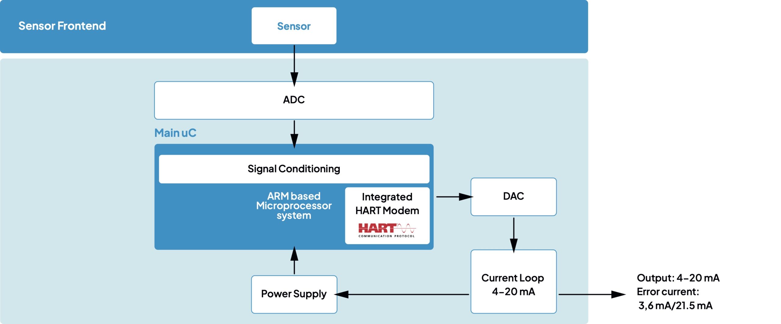
Step 1: Consideration of the Sensor Frontend
It is crucial to ensure as early as possible that the existing argumentation regarding the suita-bility and diagnosis of the sensor in terms of functional safety and explosion protection with-stands the current standards and requirements of a certifying authority. Therefore, MESCO recommends prioritizing and clarifying this part before starting with transmitter concepts based on the sensor.
Step 2: Communication Interfaces
After considering the sensors, the communication properties of the field device play a very important role. The ability to transmit measured values, parameters, and diagnoses in real-time forms the basis for modern Industry 4.0 applications with optimized processes. The system design and communication requirements are specified.
Modern field devices utilize the new standard defined for process automation, Ethernet-APL, an Ethernet- based 2-wire communication interface suitable for both powering the field devices and for use in hazardous areas. Various software protocol variants can be implemented on this physical interface: Standard Ethernet TCP/IP, HART-IP, PROFINET, OPC UA, and others. The selection of suitable communication stacks is based on the respective development requirements, such as PA-DIM support, functional safety requirements, and market demands.
Step 3: Definition of Device Profile
Once the basic communication interfaces are determined, the field device profile is defined based on it. This involves identifying and logically grouping measured values, diagnoses, warnings, alarms, internal variables, and parameters. Communication profiles from the Field Device Integration (FDI) specification, as well as HART, PROFINET, and OPC profiles, as well as existing field device parameter sets from device description files (EDDL/GSD), are considered. Additionally, parameters for Industry 4.0 / IoT use cases (PA-DIM) and safety parameters can be added.
Step 4: Development of Field Device Architecture
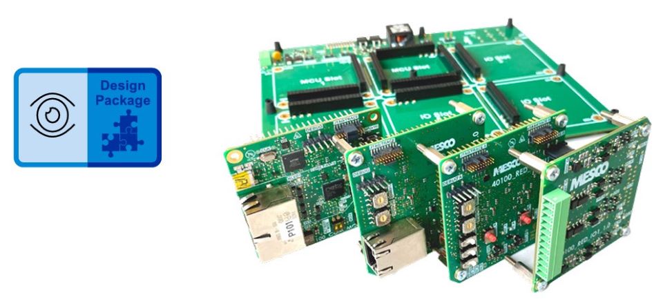
After the conceptual phase, detailed hardware and software requirement specifications (HWRS/SWRS) are developed. In this step, system requirements are translated into concrete hardware and software specifications, and the possible use of MESCO Design Packages is evaluated and analyzed. Communication interfaces, safety requirements and explosion protection requirements are derived. The implementation of measurement algorithms, diagnoses, warnings, alarm handlers, I/O handlers, and communication interfaces is described. After this phase and approval of the concepts, the prototype implementation begins.
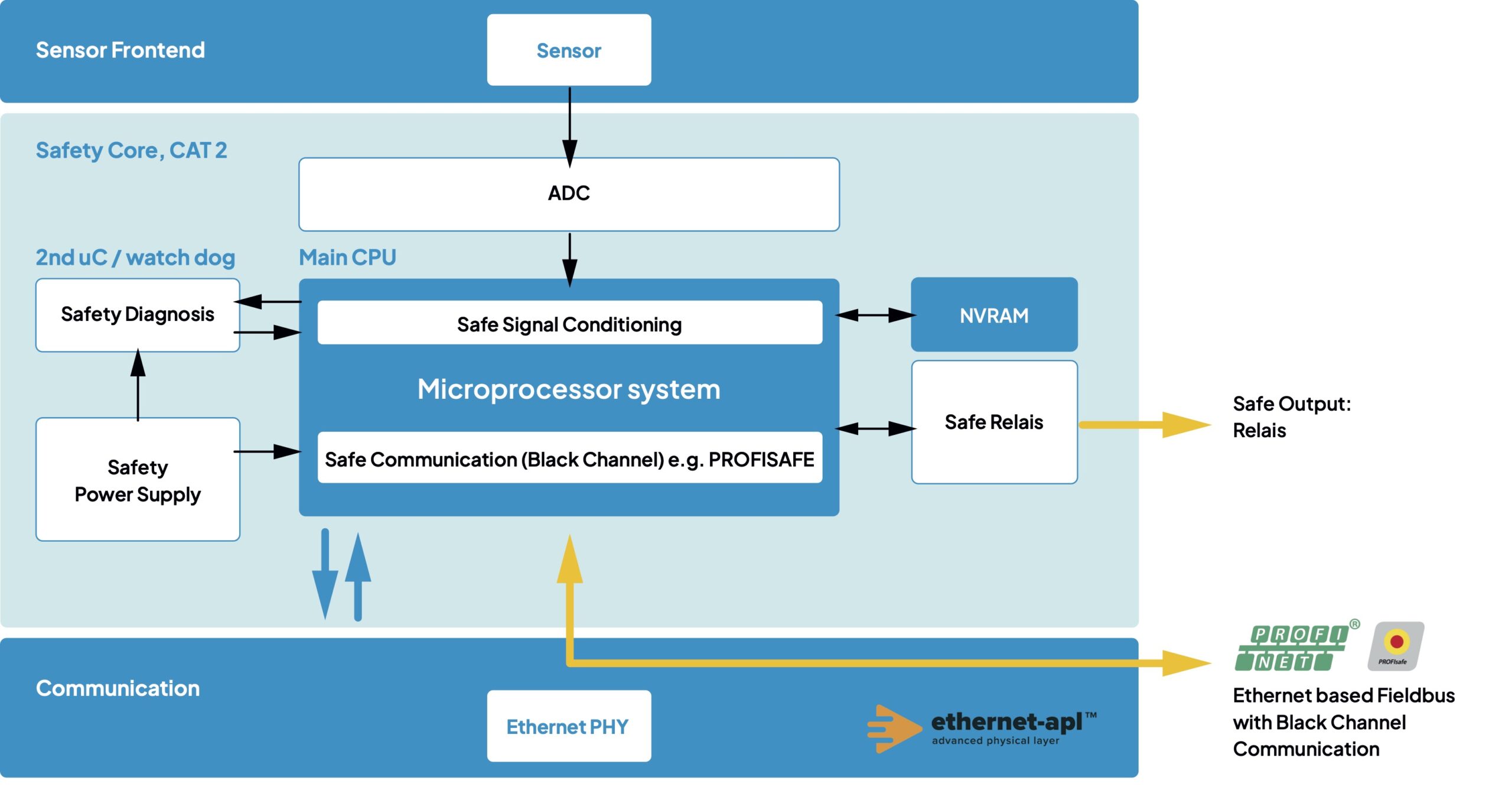
For field devices with requirements for functional safety and an Ethernet-APL interface, a block diagram could look as follows:
Steps 5 and 6: Development of Field Device Hardware and Software as a Prototype
The hardware is developed according to the defined specifications, including circuit diagrams and printed circuit board layout, with strict adherence to explosion protection and safety requirements. In parallel, the software base system is implemented, and communication stacks as well as the required algorithms are integrated with the field device profiles.
If the device must meet functional safety requirements, this significantly influences the development of field devices. The development process adheres to safety standards (IEC61511, IEC61508). These measures must be consistently followed from conception to certification of the device.
Step 7: Development of the Device Descriptor Files
The final step involves the development of an FDI package for the parameterization of the field device. Depending on the host platform, various configuration and parameterization files are created for the field device to ensure compatibility with standard host systems. This may include the implementation of a GSD file, an Electronic Device Description (EDD), or the creation of an FDI file with a graphical user interface (UI) for FDI-compatible asset management systems. Subsequently, the field device and the corresponding description file are tested for conformity with the fieldbus organization.
 Peter Bernhardt