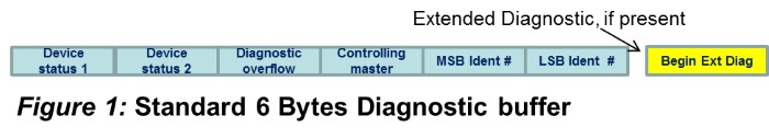
PROFIBUS’s success in the industrial controls universe is partly due to its wide array of diagnostic capabilities. Every PROFIBUS slave device must support, at a minimum, 6 bytes of standard diagnostic data. This data is defined by PROFIBUS and PROFINET International and reports the device state, its controlling master and whether the device has any extended diagnostic data (additional fault information) available.
Editor’s Note: This is the second of a series of tech tips that explain how PROFIBUS diagnostics work and how they can be used to make critical information available to a PLC or DCS. The first tech tip is here.
 PROFIBUS Extended Diagnostic Information may be encoded in 3 different formats: Device Related Diagnostic, Identifier Related Diagnostic and Channel Related Diagnostic. The first two bits of the diagnostic block indicate the encoding. For Device Related and Identifier Related, the remaining 6 bits tell us the total length of the diagnostic block, including the header. For Channel Related diagnostics, the block is always 3 bytes long. An Extended diagnostic may contain one or more of these blocks in any combination.
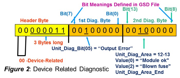
Device Related Diagnostics are designated by the two most significant bits being set to 0 0. The possible meaning of the bits is completely up to the device vendor (PROFIBUS and PROFINET International does not specify the meaning of the bits). Usually the Vendor describes the meaning of the diagnostic bits in the slave GSD file. See figure 2.
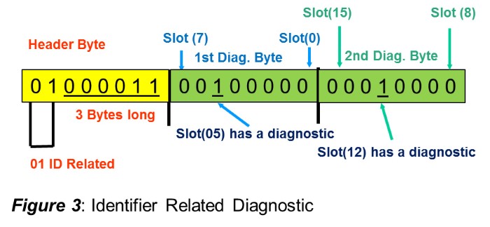
 Identifier Related Diagnostics are designated by the two most significant bits in the diagnostic header being set to 0 1. Each bit in the following bytes of the ID Related Diagnostic represents a plug-in module with a diagnostic condition. See Figure 3.
 Channel Related Diagnostics are designated by the two most significant bits in the diagnostic header being set to 1 0. The information available in a Channel Related
 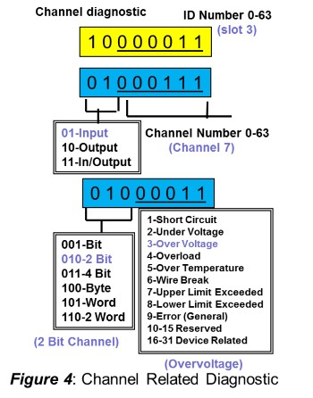 diagnostic includes the module number within the slave, the input/output type, the channel size, the channel within the module with the diagnosis and a diagnosis code for the problem that was detected. Please see figure 4 for the details.
Many devices support all three types of extended diagnostics, and some even allow the selection of which type/types of diagnostics to report as a parameter.
In order to fully take advantage of the diagnostic possibilities, the application code in the PLC/DCS must be able to read the diagnostic buffer of a slave reporting extended diagnostics. It must decode the diagnostic information and display it in a form that is easily understood by the maintenance personnel.
John Swindall, PROFI Interface Center