Over the past few years, IO-Link has established itself as the standard interface for the sensor/actuator level. International standardization in IEC61131-9 and fieldbus neutrality are certainly two of the most important factors responsible for the very impressive distribution seen today. In the meantime, a broad base of very diverse sensor and actuator technologies with IO-Link interfaces has become available. Today, more than 13,000 different IO-Link products can be found on the market altogether.
The standardization of IO-Link extends far beyond communication, though, as basic functions like identification and diagnosis are defined for all devices in the standard, for example. There’s also the IODD (I/O Device Description), a system-independent description method for IO-Link devices with which the devices can be integrated into and operated on different systems with a variety of tools. The usual requirements for automation applications in factory automation are met with the maximum cable length of 20 meters between the master and terminal and a typical process data update rate of 1 to 5 ms.
Further development of Ethernet-based communication interfaces has intensified over the past few years. In the industrial environment in particular, Ethernet has fully established itself as the basis for fieldbus connections. Another driving force for Ethernet-based communication in the industrial environment is of course the connection or integration of classic automation applications into IoT applications within the scope of Industry 4.0 requirements.
The relatively new developments and standardization towards SPE – or Single-Pair Ethernet – come into the focus especially for industrial applications. The simple twisted-pair cable serves for both data transfer and the supply of power. This also makes it possible to operate terminal devices – sensors or actuators – on the lower field level with sufficient data bandwidth. SPE has since become a market-ready standard for industrial use.
Will the penetration of SPE into industrial applications down to the lower field level displace IO-Link, or can IO-Link and SPE coexist? Could there even be a solution which combines the advantages of IO-Link and Single-Pair Ethernet?
The IO-Link community also addressed these questions and came to a relatively simple, yet very promising approach which was published as a concept study at the beginning of the year.
Single-Pair Ethernet (SPE) – A New Standard for Industrial Automation
SPE involves a series of standards which are all build upon the standards of the IEEE 802.3 family and which use a standardized structure of the Ethernet frame. Only the definition of the physical layer, i.e. the connection layer, is exchanged here. The SPE standards differ significantly in terms of the defined transfer rate.
- 10Base-T1 – 10 Mbps, twisted-pair
- 100Base-T1 – 100 Mbps, twisted-pair
- 1000Base-T1 – 1000 Mbps, twisted-pair
For industrial use, 10Base-T1 is of primary interest today. The associated standard – IEEE 802.3cg – was adopted and published at the beginning of this year and contains definitions of three versions.
- 10Base-T1S (short-reach)
- 10Base-T1L (long-reach)
- APL (Advanced Physical Layer – intrinsically safe)
10Base-T1S is multi-drop capable, meaning that multiple devices can be connected to a single line. The cable length is limited to between 15 and 25 m here, however. As the “L” in its name suggests, 10Base-T1L is the long-range version. 10Base-T1L defines a point-to-point connection and permits a cable length (twisted-pair) of up to 1,000 m with up to 60 W of power for the terminal device. With regard to communication, APL is fully compatible with 10Base-T1L, but does not support the performance classes defined there. Due to the special explosion-protection requirements down to zone 0, the available power for the terminal device is limited to approx. 500 mW with APL. In addition, the maximum cable length is reduced to 200 m as compared to 10Base-T1L. Semiconductor solutions for these SPE interfaces which will support 10Base-T1L and APL are currently being developed.
What is IO-Link-over-SPE?
In common factory automation applications, IO-Link easily meets most requirements. As the portfolio of IO-Link devices constantly grows and the areas of application expand accordingly, IO-Link is in some cases coming up against technological limits. For example, there are definitely requirements for transferring IO-Link over greater distances than the given limit of 20 m. Requirements on IO-Link communication in explosion-protected areas are also known, and solutions which can meet these requirements are now available with SPE 10Base-T1L and APL.
Does the IO-Link system therefore have to be left for such applications?
Ethernet is usually associated with TCP/IP- or UDP-based communication. TCP/IP communication requires considerably more complex firmware structures in comparison to IO-Link and compliance with the stringent security requirements in the terminal devices. Thus, the ability to communicate would probably only be reserved for more complex terminal devices. If the IO-Link devices in use today were equipped with TCP/IP communication, the number of IP addresses required would litarally explode. The ease of integration of IO-Link devices into different system environments would also change substantially.
So why not keep the existing IO-Link system and enhance it with another physical interface? This is precisely the approach of the IO-Link-over-SPE concept. With IO-Link-over-SPE, the IO-Link messages are packed into Ethernet frames and then transferred via an SPE driver over a twisted-pair line instead of the IO-Link messages being transferred as pulse-encoded telegrams over the classic 3-lead cable at 24 V – without TCP/IP or UDP. As the following graphic shows, the core components of IO-Link communication, the implementations of the protocol layer and the functions remain unchanged.
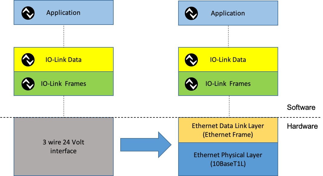
In other words, IO-Link is still IO-Link. Integration into higher-level systems also remains the same – only the communication medium is exchanged. The following mapping shows the embedding of the IO-Link message structure into an Ethernet frame. This means that a specific user data structure characterized by an “EtherType” in the Ethernet frame is required for IO-Link. Consequently, a separate “EtherType” is required for the IO-Link-specific mapping shown.
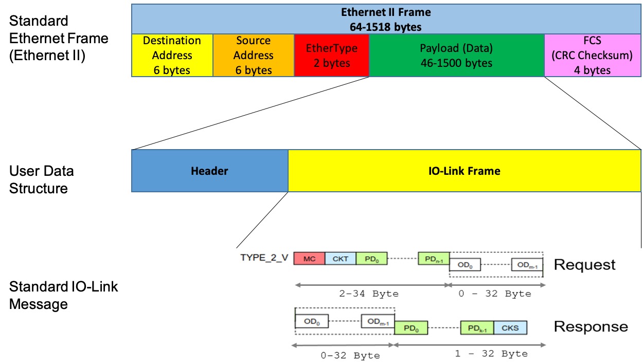
A complete IO-Link message fits into each Ethernet frame or in the user data. In fact, the IO-Link message is usually considerably shorter than the minimum possible user data length of the Ethernet frame. This means that more data is transferred than required. The resulting cycle time for exchanging Ethernet frames – and thus IO-Link messages as well – is still considerably shorter than with standard IO-Link due to the transfer rate of 10 Mbps. Future enhancements or changes can be made to the protocol using the header shown.
The method for embedding the existing message structure of IO-Link unchanged into an Ethernet frame is the main idea behind IO-Link-over-SPE. This procedure is also the key to easy migration to SPE – IO-Link-over-SPE – and the reusability of implementations and tools.
Unchanged Structure; New Application Scenarios
How is an IO-Link-over-SPE system then integrated into an existing system structure? As expected, there aren’t actually any noteworthy differences other than the replacement of the standard 3-lead cable with the twisted-pair SPE cabling.
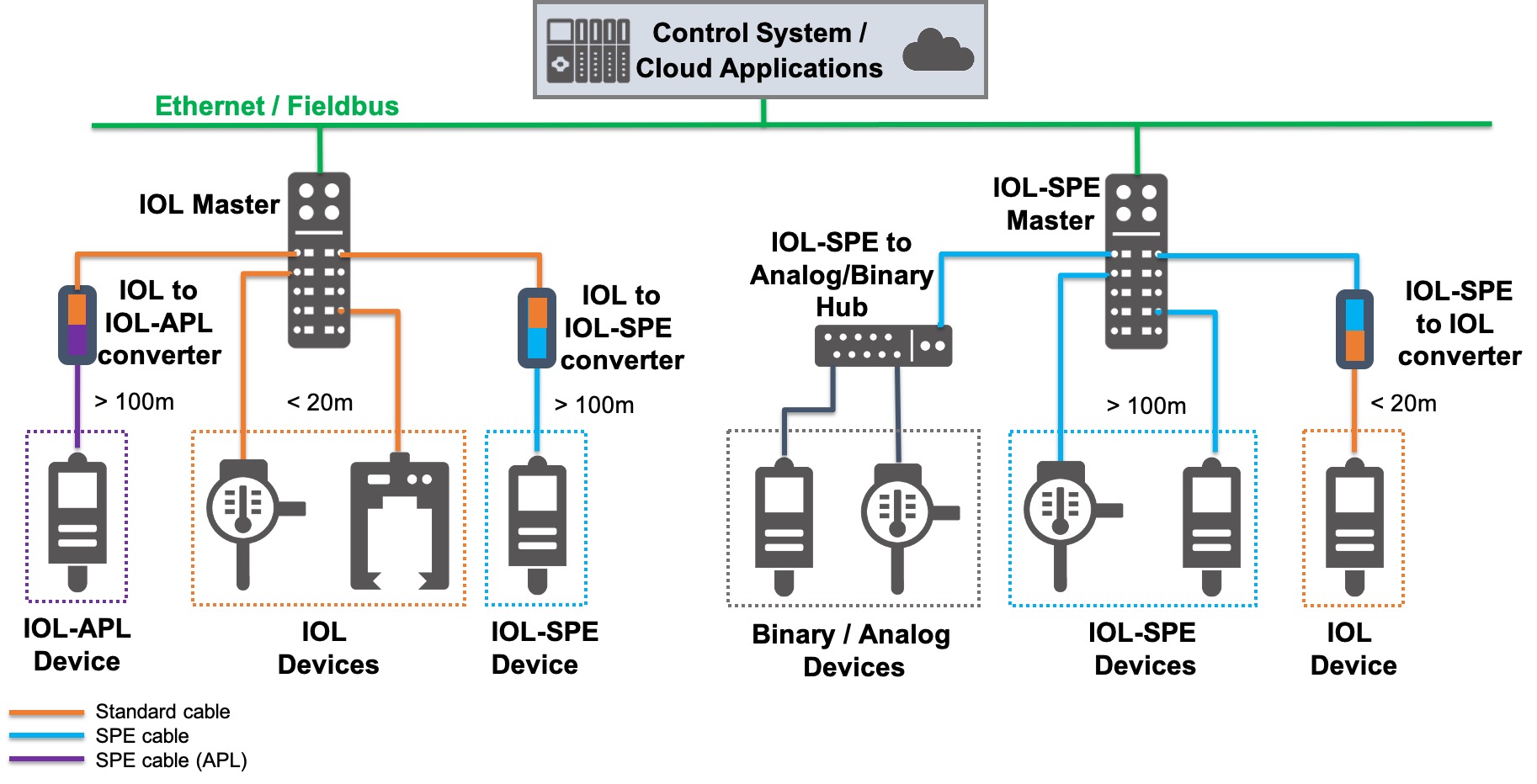
The IO-Link masters with standard IO-Link ports are replaced with IO-Link masters with SPE ports. Likewise, IO-Link devices now receive SPE interfaces and are also supplied with power directly over the twisted-pair line from the master. The potential distance between the master and IO-Link device increases to well over 100 m (maximum 1,000 m) in the case of the SPE system. In addition, IO-Link-over-SPE also features hubs which collect and transfer the binary or analog signals of the connected terminal devices over IO-Link as usual, but now over the SPE interface.
Due to the now different physical characteristic of the connection level, the idea of converters is only natural. An application where a single or a few terminals would be located more than the maximum permissible distance of 20 m away from the master in a standard IO-Link system can be covered by a converter from standard IO-Link to IO-Link SPE. The corresponding terminal device then features an SPE connection. The reverse case is possible as well, of course. If a terminal device which is only available with the standard IO-Link interface is to be connected to an IO-Link SPE master, a converter from IO-Link SPE to standard IO-Link can remedy the situation. The case that a single terminal device is to be used in a system with standard IO-Link components in an environment with explosion-protection requirements can be covered by an IO-Link to IO-Link APL converter.
What could a possible structure for an application in an intrinsically safe environment look like?
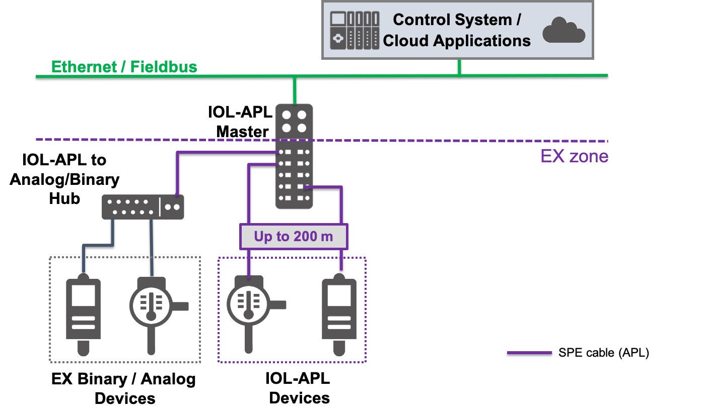
The basic structure between an IO-Link master and terminal devices in the intrinsically-safe environment is identical to the existing structure in the environment with standard IO-Link. An APL (Advanced Physical Layer) version of SPE interface physics is used. The distance between the master and terminal is thus limited to 200 m. Corresponding measures are now to be taken in the IO-Link APL master to ensure the intrinsically safe separation of the power supply and communication with the higher-level system.
A possible approach where a hub captures analog or binary signals from intrinsically safe terminals and transfers them together over IO-Link APL to the master would also be conceivable for the intrinsically safe application.
An Enhancement with Future Potential
IO-Link over SPE is not another Ethernet-based bus system. Just like standard IO-Link, it is a point-to-point connection without addressing. All the defined interfaces and functions are retained. Established IO-Link integration standards like IODD, the OPC UA companion standard, JSON mapping and fieldbus integration can still be used in the exact same way. In combination with the IO-Link Safety Profile, safety-oriented applications can also be implemented with IO-Link-over-SPE.
This makes IO-Link-over-SPE a fully compatible extension of the IO-Link standard with the following advantages:
- Line lengths up to 1,000 m (200 m with APL)
- IO-Link communication for intrinsically safe applications
- Process data cycles are approx. 20 times faster
- Easy integration, just like standard IO-Link
- Considerably fewer security requirements in comparison to TCP/IP
Will IO-Link-over-SPE replace the widely used standard IO-Link interface? Certainly not. As of today, IO-Link-over-SPE is a concept study which points out opportunities for increased performance in conjunction with a considerably broader application focus. An SPE interface in an IO-Link terminal device will also result in higher costs as compared to the standard for the foreseeable future. For this reason, the existing 3-lead, 24 V-based IO-link interface will still be used for the large number of existing cost-sensitive applications. IO-Link-over-SPE can be seen as a consequent extension of the IO-Link standard with lots of potential for the future.