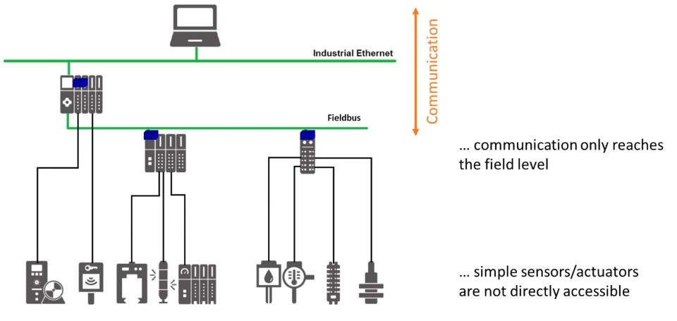
In the last issue of PROFINEWS, we reported on the impressive node counts for all of the PI technologies. IO-Link is one of those technologies, and it continues to outperform expectations. With the number of IO-Link nodes soaring to just over 51M at the end of 2023, let’s take a closer look at what’s behind the success of this technology. If we remember not too long ago, in the traditional automation hierarchy, communication only reaches down to the Fieldbus level. Sensors and actuators are not directly accessible by the network because these cost-effective devices only communicate with simple digital I/O or simple analog I/O.
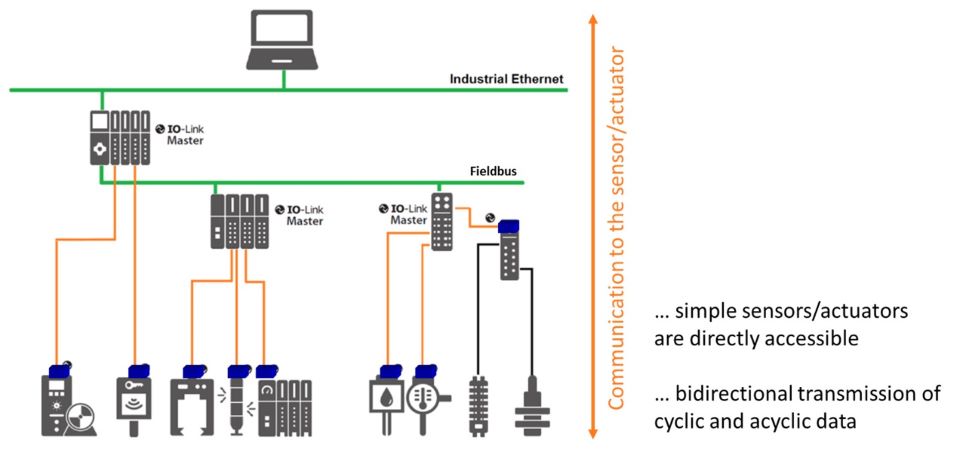
Now, with IO-Link to the “Last Meter” sensors and actuators are directly accessible because they use bidirectional serial communication for both cyclic and acyclic data rather than just a simple input or a simple output.
As memory and computing power have gotten really, really small and really, really cheap, we are starting to see devices in the market that have a lot more capability in them. Now you can make a device smart – so it knows, for example, not only if a box is present or not, but if it is a red box or if it is a blue box. The device may even know how many red boxes went by and how many blue boxes went by. But you aren’t going to put a $5 Ethernet chip in a $15 proximity sensor. It makes no sense. And this is where IO-Link comes in. It is an inexpensive, powerful technology that provides access to all of the data available in these intelligent devices.
IO-Link is not a fieldbus, but a simple point-to-point communication protocol. At its highest level, IO-Link consists of four components types: a Master, some number of Devices, a set of IO-Link cables, and an IODD file for each Device.
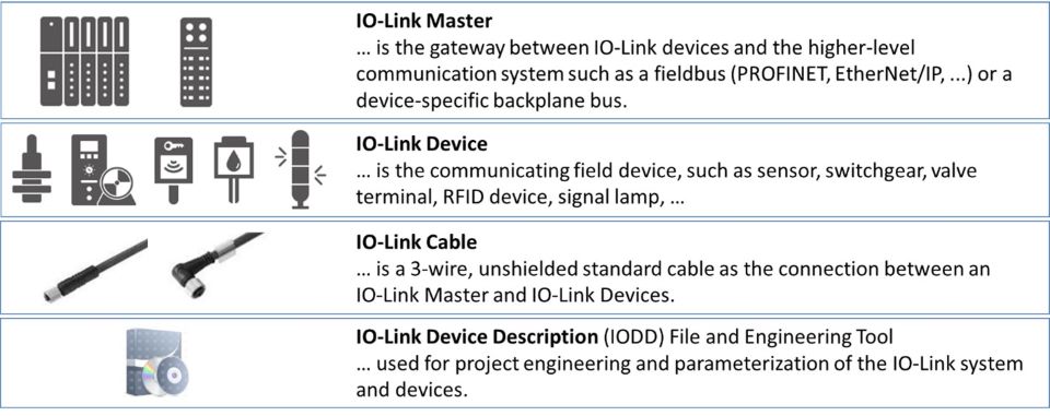
The Master is really just a gateway between Devices and a higher-level network like PROFINET, or the Master can be integrated in the PLC over its backplane. Devices can be just about any sensor, actuator, or indicator, and these Devices connect point-to-point to the Master using a cost-effective, unshielded cable. The IODD file is analogous to a GSD file because it describes the characteristics of the IO-Link Device, and it is used by the IO-Link Master for device parameterization. A really nice feature of IODD files is that they are available in a centralized database called an “IODD Finder”. These files are accessible by a human using a web interface or by a machine using an Application Programming Interface.
The IO-Link interface consists of 5 pins with 2 Port Classes. Port Class A has 2 pins for Power, 1 pin for Data, and 2 pins are Spare. Data can be either a bidirectional serial signal or a simple digital signal. This simple digital signal is used to connect non-IO-Link devices, and is called Standard IO, or SIO.
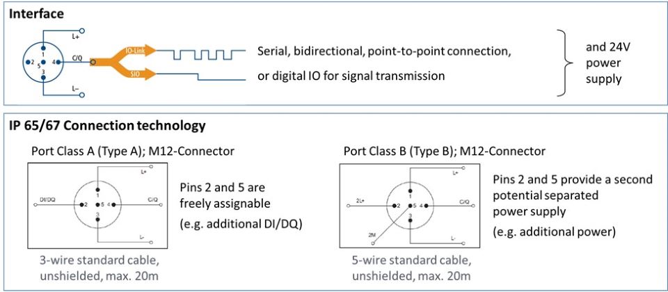
Port Class B is the same as Port Class A except the 2 Spare pins are assigned an additional power supply. This additional power supply is useful for devices that require more power like linear actuators. In either case, you use an IO-Link cable that can be up to 20m in length.
And those are the reasons behind its success. Simplicity along with ease of use. If you haven’t looked into IO-Link, now is the time. It is a great way to unlock all of the great data available in these new intelligent devices.