Testing PROFIBUS Networks
Recently, Softing received a support call from one of the largest producers of carbon fiber. Part of the carbon fiber production process was controlled by a PLC communicating over PROFIBUS with multiple devices. Within the last few months, the customer experienced a dramatic increase in PROFIBUS network faults that forced the PLC into stop mode, jeopardizing the product quality.
The conventional approach to diagnose network problems by using network monitoring tools and frame analyzers did not reveal any significant problems. Everything looked just fine. So, why did the PLC go into stop mode?
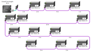
Softing sent an experienced support engineer on-site. Since the customer had already checked the data using networking monitoring and frame analyzers, the Softing engineer decided to start by analyzing the electrical signal characteristics. The engineer attached a PROFIBUS Tester to the network to automatically determine the network topology and to analyze the signal quality for each active node on the network at multiple locations.
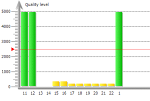
The first check the engineer performed was something called a signal quality test which is an overall composite of several signal tests which are required for proper PROFIBUS performance. Figure 2 shows us a red horizontal line, which is the minimum acceptable level of 2500. All the green bars (PROFIBUS devices/nodes) are well above the line and are good.
The yellow bars are well below the line: not good. And two devices, 13 and 14, appear to be at zero.
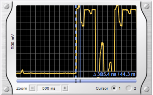
The green/yellow/red bars are the results of the signal-processing by the tester, but the engineer wanted to have a look directly at the signal with the oscilloscope function (Figure 3; tester was connected to the device with node address 22). What you should see in the oscilloscope view is a nice rectangular signal, but what he saw was a distorted signal that showed signal reflections on the cable trunk. Signal reflections are typically caused by bad connectors or missing bus termination. The engineer was able to determine that the reflection occurred approximately 45 meters away from that node which identified a location at the “other end” of the network.
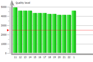
The “other end” of the network was adjacent to the PLC. The first step was to check the PROFIBUS connector bus termination setting. It was correctly set to “On.” The next step was to inspect the connector itself. The bus termination circuit within the connector was found to be faulty. After replacing the faulty PROFIBUS connector, the correct bus termination was restored, the signal quality of the network returned to an acceptable level, and the PROFIBUS network faults that created the PLC stop mode issue (the PLC was not able to receive every data frame because the signal was too distorted) was eliminated.
To get a complete picture of the health of your PROFIBUS network, it is important to evaluate all aspects… cable/connectors, topology, packets, and do not forget signal. In this case, the built-in oscilloscope of the tester significantly assisted in locating signal issues on your RS485 network.
 Jeff Besola