Abstract
Communication of data between various devices is essential in many aspects of daily living. The proliferation of devices and the dramatic increase in data volumes driven by digitalization and Industry 4.0 are forcing changes in the communication landscape. For example, in areas such as process automation, integrated networks that support connectivity across entire factories are required. Data must be extracted from operational technology (OT) machines, processed, and then supplied to computer systems at the company level (IT) for further processing. As the previous 4–20 mA or fieldbus applications run up against their limits in terms of data communication, Ethernet is emerging as the communication standard. Primarily, this is the new Ethernet standard 10BASE-T1L, a 2-wire Ethernet solution for line lengths of up to 1000 m at a transmission speed of 10 Mbps with support for transmission protocols such as PROFINET. With this standard, it is possible to continue using existing 2-wire cabling and thus protect investments.
This article explains the basics of 10BASE-T1L and shows corresponding products that are also relevant in the selection of suitable connectors for various applications. Power transmission of the various connected devices via the data line also plays an important role with 10BASE-T1L.
Introduction
Data communication is taking on an ever-greater role not only in the industrial sector but also in process automation. The previous 4–20 mA or fieldbus applications are reaching their limits due to burgeoning data volumes, and Ethernet is thus crystalizing as the communication standard. The standard Ethernet, 4-wire solution has evolved into a 2-wire solution known as 10BASE-T1L, consisting of a single pair of twisted cables or single-pair Ethernet (SPE). Above the physical layer, 10BASE-T1L is compatible with existing Industrial Ethernet technologies with 100 Mbps or 1000 Mbps and thus is a supplement.
10BASE-T1L is becoming standardized especially in process automation and has the potential to effect sweeping changes in this area. Precisely here, up to now, sensors and actuators have usually been connected via a 4–20 mA analog interface or a fieldbus. In process automation, unlike in mechanical engineering or plant automation, these sensors and actuators are usually at a distance to the control system or the remote I/O systems. Distances of 200 m to 1000 m or more are common.
But what exactly is 10BASE-T1L, what advantages does this technology offer, and why is it a new standard?
These questions will be answered in the following sections.
What Does 10BASE-T1L Mean?
The name 10BASE-T1L roughly explains its meaning. The Institute of Electrical and Electronics Engineers (IEEE) abbreviations are used here.
The “10” in the medium type references a transmission rate of 10 Mbps. “BASE” refers to baseband signals, which means that only Ethernet signals can be transported over the medium. “T” stands for “twisted pair.” The digit “1” stands for 1 km range. In this case, it is followed by an “L” for “long range,” meaning that segment lengths of 1 km and more are possible.
There are still other network technologies, such as 10BASE-2 (thin coaxial cable with a maximum segment length of 185 m), 10BASE-5 (thick coaxial cable with a maximum segment length of 500 m), 10BASE-F (fiber optic cable), or 10BASE-36 (broadband coaxial cable with multiple baseband channels and a maximum segment length of 3600 m).
Which Layer of the OSI Model Can 10BASE-T1L Be Categorized Into?
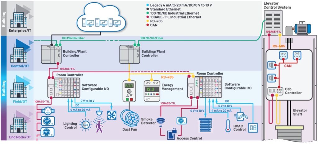
10BASE-T1L offers the possibility of using the existing 2-wire infrastructure to realize line lengths of up to 1000 m at a transmission speed of 10 Mbps. The physical Ethernet technology is defined exclusively in Layer 1 (the bit transmission layer or physical layer) of the Open Systems Interconnection (OSI) model. Above the bit transmission layer, 10BASE-T1L supports common Ethernet protocols such as PROFINET, as well as other bus systems, such as BACnet, KNX, and LON, that are commonly used in building management systems.
10BASE-T1L is implemented with the help of a special Ethernet PHY in Layer 1. The Ethernet frames are transmitted between MAC and PHY via the media-independent interface (MII), reduced MII (RMII), or reduced gigabit MII (RGMII).
The MAC is defined by the Ethernet standard IEEE 802.3 and implemented in the data link layer (Layer 2). The PHY forms the physical interface and is responsible for coding and decoding the data between the transmission medium and the digital system.
With Which Devices and Machines Can 10BASE-T1L Be Used and To What Extent Can the Existing Infrastructure Be Used with It?
10BASE-T1L is designed to replace the 4–20 mA standardized signal in many, if not most, process automation applications. However, this does not mean that older field instruments connected via 4–20 mA current loops will have to be replaced with 10BASE-T1L–capable field instruments. These conventional devices can be connected via software configurable I/O (SWIO) modules, while remote I/Os serve as a collection point for connection to the PLC with a 10 Mbps Ethernet uplink.
Software configurable I/O modules have reconfigurable module channels, which allows them to work quickly, easily, and remotely without requiring extensive rewiring. The channels can be configured either as input or output both for currents and voltages, or digital and analog.
In some cases, there is a requirement that both power for the devices and their data be provided via 10BASE-T1L, which is defined as part of the standard. Figure 1 shows an example of a mix of conventional field instruments connected via a 4–20 mA current loop and new 10BASE-T1L-capable field instruments.

10BASE-T1L supports two amplitude modes: 2.4 V for cable lengths of up to 1000 m and 1 V for shorter distances up to 200 m. Through the 1.0 V peak-to-peak amplitude mode, this technology can also be used in explosion-protected environments (hazardous areas) and meets the strict maximum energy consumption requirements applicable there.
An industry consortium has specified the advanced physical layer (APL), which builds on the 10BASE-T1L standard, defining intrinsically safe operation for process automation.
Ethernet-APL likewise enables the transition to seamless process automation installations with field-to-cloud connections, including areas with potentially explosive atmospheres for installations in the food and beverage, pharmaceutical, and oil and gas industries. Furthermore, APL also defines the power provisioning classes over the single twisted pair lines.
No concrete transmission medium (cable) is defined with 10BASE-T1L. Only the requirements for return loss and insertion loss of the cables are specified. Fieldbus Type A are the cables of choice here. This allows the reuse of existing PROFIBUS cabling. 10BASE-T1L works with a balanced pair of conductors over a cable length of up to 1000 m without any problems. However, in noisy industrial environments, a shielded cable like Type A cable is required—using connectors, screw terminals, or punch-down blocks. Some 10BASE-T1L switch chips have integrated diagnostics functions that check the signal quality over the cables. 10BASE-T1L is thus a very robust communication technology—even a mix-up of the wires does not pose a problem.
What Are the Advantages of 10BASE-T1L?
Conventional 4–20 mA and fieldbus devices have a limited data bandwidth of just a few kbps. With 10BASE-T1L, speeds of 10 Mbps can be reached. This makes it possible to transmit not only a process value but also additional device parameters such as configuration and parameterization information. In the future, possible software updates for the increasingly complex sensors, as well as fault and network diagnostics such as short circuits on the line to the sensor, will be performed relatively quickly via the data line. Configuration is also easier because gateways and converters are no longer required with 10BASE-T1L. Through the elimination of the gateways, the costs and the complexity of these old installations are greatly reduced, and the data islands created by them are swept away.
In addition, higher powers can be transmitted over the data line. For example, 500 mW in intrinsically safe areas (hazardous areas) and even up to 60 W in non-intrinsically safe areas can be transmitted.
Ethernet standards such as PROFINET and OPC UA, or IoT protocols such as MQTT, can enable the easy and powerful connection of field devices to a cloud.
Does 10BASE-T1L Also Work with Switch Modules?
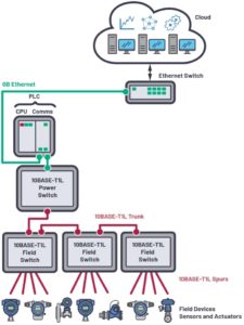
As with standard Ethernet, with 10BASE-T1L there are bridges that enable coupling of various network segments and devices. Different network topologies can be realized and used to supply power to the connected devices. In process automation, switches are often connected to controllers, HMIs, and the cloud. Switches allow media redundancy in the form of ring topologies for increased availability.
In process automation, the connections to the devices, sensors, and actuators are also called spurs, whereas connections between the switches and running up to the control system fall under the name trunk.
Further possibilities arise from the constantly increasing integration density of devices. For example, a 10BASE-T1L switch can be integrated into a sensor connected directly to additional sensors that can also be supplied by it. Figure 2 shows an exemplary interconnection of different switches.

Communication with a 10BASE-T1L–capable device takes place via the host processor. It usually requires an integrated MAC function, a passive media converter, or a switch with 10BASE-T1L ports.
Table 2. Overview of the Different Communication Technologies in Process Automation
| 4–20 mA with HART | Fieldbusses | 10BASE-T1L | |
| Data Bandwidth | 1.2 kbps | 31.25 kbps | 10 Mbps |
| Connection to Higher Level Ethernet Networks | Complex gateways | Complex gateways | Seamless connectivity without gateways |
| Power Offering for Instrument | <40 mW | Limited | Intrinsically safe: 500 mW; non-intrinsically safe: up to 60 W (depending on cable) |
| Know-How/Expertise | Know-How/Expertise shrink | Know-How/Expertise shrink | University graduates are very familiar with Ethernet |
Can I Also Implement the Power Supply to the Devices via the “Two Wires”?
The 10BASE-T1L standard not only offers communication of data from sensors and actuators, but also provides the possibility of supplying them with power via the signal lines. Concretely, 10BASE-T1L can deliver up to 60 W of power in non-intrinsically safe areas. In explosion-protected (intrinsically safe) areas, the power is limited to 500 mW; in this case, the signal amplitude is also reduced from that of standard applications from 2.4 V to 1 V to comply with the strict requirements for maximum energy applicable there. However, as a result, only reduced transmission distances are possible in intrinsically safe areas.
Table 3 provides an overview of the possible power transmission levels for the various line lengths and areas for a Type 18 AWG cable.
Table 3. Overview of Power Transmission Levels at Different Cable Lengths (Type 18 AWG)
| 55 V | 24 V | |
| 1000 m | 7.7 W | 1.23 W |
| 400 m | 20 W | 3.2 W |
| 150 m | 52 W | 8.3 W |
Conclusion
10BASE-T1L provides a relatively robust communication standard for process automation that offers numerous advantages over conventional 4–20 mA applications, including the possibility of reusing the existing infrastructure.
About the Authors
Thomas Brand began his career at Analog Devices in Munich in 2015 as part of his master’s thesis. After graduating, he was part of a trainee program at Analog Devices. In 2017, he became a field applications engineer. Thomas supports large industrial customers in Central Europe and also specializes in the field of Industrial Ethernet. He can be reached at thomas.brand[AT]analog.com.
Thomas Tzscheetzsch joined Analog Devices in 2010 working as a senior field applications engineer. From 2010 until 2012 he covered the regional customer base in the middle of Germany. Since 2012 he has worked in a Key Account Team on a smaller customer base. After the reorganization in 2017 he started leading a team of FAEs in the IHC cluster in CE as an FAE manager. He can be reached at thomas.tzscheetzsch[AT]analog.com.
