Shedding some light on the use of Fiber Optics in PROFIBUS
We’ve always used the default values…
While analyzing some communication issues in a customer’s PROFIBUS DP network, we quickly realized that the bus parameter settings that were being used in the controller’s DP Master configuration were the default values for the 1.5 Mbps transfer rate. These values have been employed in most applications without issues since they were initially specified a long time ago.
But these values are meant to be used in standard copper cable PROFIBUS DP installations. Nowadays PROFIBUS DP applications are built not only on copper cable but also on fiber optics (FO), made possible through Fiber Optic Link modules (FOLs).
Some optical background…
As you may surely know, the native physical layer of PROFIBUS DP is based on the RS485 physical layer standard using NRZ encoding. Differential voltage mode and 2 wires twisted shielded cable is used to minimize EMC issues. The traditional PI recommendation for DP copper networks grounding is to use hard grounding for both ends of the cable shield for optimal EMC protection, this requirement also implies the need for equipotential grounding.
This is usually not an issue for short low speed (<1.5 Mbps) network segments but it becomes increasingly difficult for longer high-speed ones.
In the past, it was usual to encounter current loop issues in long PROFIBUS DP cable runs. The longer the cable run, the harder it was to achieve equipotential grounding.
You got free from those annoying ground current loops but…
This changed dramatically when FOLs became available. FOLs not only allow the use of a redundant communications backbone that extends the achievable distances to several kilometers, but they also eliminate equipotential grounding requirements.
Since a FOL is basically built onto an optocoupler, it works as a galvanic isolator. So, this architecture allows the creation of a galvanically isolated fiber optic network backbone that can cover the entire plant. Then you can use copper at the points where the devices are located. Shorter copper cable runs are much easier to ground properly and the risk of current loops due to improper grounding is greatly diminished.
But there is a catch: Although for PROFIBUS DP any kind of physical media conversion is transparent (fiber optic or radio links), each media conversion requires some signal processing and re-encoding. And these processes take some time to complete.
Enter the magnificent but usually misunderstood world of PROFIBUS DP bus parameters.
Tsl, Ttd, tbit, Tsm, Tsdr, Tid… wth…
These parameters are also known as timings and consist of a collection of values that enable the real-time cyclic and acyclic communications defined by the PROFIBUS standard. They are expressed in a unit called bit time, which is the time required to transmit a bit at a specified baud rate (1 tbit = 1/baud rate).
One of the most critical timing values is the one known as Slot Time (Tsl). There are several definitions of the meaning of this parameter but for consistency purposes, I’ll take the definition of the official PROFIBUS specification:
“The Slot Time Tsl is the maximum time the initiator waits for the complete receipt of the first frame character (being the first character 11 bit long) of the immediate acknowledgment of response, after transmitting the last bit of an action frame.
Furthermore, Tsl is the maximum time the initiator waits for the token receiver’s first frame character after transmitting a token frame.”
Do the math…
Theoretically, two Slot Times are distinguished, corresponding to the two types of communication possible in PROFIBUS. Communication between Masters employs the token frame, and communication with the slaves is done by action frames. First, let’s define some variables.
Max Tsdr is the Maximum Responder Delay. It is defined in the GSD file for the slave and depends on the bit rate. The usual practice is to consider the maximum value of the participating stations. That means the device with the larger Max Tsdr defines the value.
Ttd is the Transmission Delay. It is the maximum delay between two communicating stations and is due to the time spent by the signal to travel through the physical medium. It depends on the cable length and number of repeaters/FOLs/media converters used.
Tsm is the Safety Margin Value. It is defined by the standard as: Tsm = 2 + 2×Tset + Tqui
In the equation Tset is the Setup Time. It is the time required for the PROFIBUS ASIC to switch from receive mode to transmit mode. The usual value is 6 tbit and it is hardware dependent. And Tqui is the Quiet Time. It is the time a station must wait after the end of a transmission before enabling its receiver. The usual value for Tqui is 3 tbit and it is hardware dependent.
Therefore, after an action frame (request or send/request) the Slot Time is calculated as follows:
Tsl1 = 2×Ttd + Max Tsdr + 11 tbit + Tsm
Yeah, sure, but what does this mean in real life…
Before calculating the slot after a token frame, we first must define a few more variables.
Min Tsdr is the Minimum Responder Delay. It is the time a slave station must wait after the end of a request before sending a response. This value is set by the controller and usually is 11 tbit.
Tsyn is the Synchronization Time. It is the minimum time that the transmission medium should be idle before a station can receive a telegram. This value is defined by the standard at 33 tbit.
Tsdi is the Initiator Delay. It is the time a master station must wait after the end of a previous response, and before sending a request, and depends on the bit rate.
Tid1 is the Idle Time. It is defined as follows: the time which expires at the initiator after the receipt of a frame’s last bit until a new frame’s first bit is transmitted on the medium. It also is the time that expires after the last bit of an unacknowledged frame has been transmitted and transmitting a new frame’s first bit.Tid1 is basically the time that exists between frames either sent or received by the Master.
So it’s a matter of timings…
There are two possible Tid values:
Tid1: This value corresponds to the time between the end of the reception of a frame and the transmission of a new frame. Tid1 = max (Tsyn + Tsm, Min Tsdr, Tsdi)
Tid2: This value corresponds to the time between the end of the transmission of a frame that does not need to be acknowledged and the transmission of a new frame. Tid2 = max (Tsyn + Tsm, Max Tsdr)
Again, the value to be taken is the longer one: Tid = max (Tid1, Tid2)
Therefore, after a token frame, the Slot Time is calculated as follows:
Tsl2 = 2×Ttd + Max Tid1 + 11 tbit + Tsm
For simplification purposes, the longer value of these two is the one used in the system:
Tsl = max(Tsl1, Tsl2)
For the monitoring of Tsl, there is a Slot Timer implemented in the Master station. This timer monitors, after a send/request or a token pass, whether the receiving station responds or becomes active within the predefined time Tsl.
After transmission of a frame’s last bit, this timer is loaded with the Tsl value and decremented each bit time as soon as the receiver is enabled.
If the timer expires before a frame’s first bit is received, an error has occurred. Then a retry or a new message cycle is initiated. Depending upon your retry settings, new retries will be performed. After the retry limit, the station affected drops out of data exchange until the Master is able to get it back into this mode.
In order to fully understand these mechanisms, let’s try with a graphic scheme of the process:
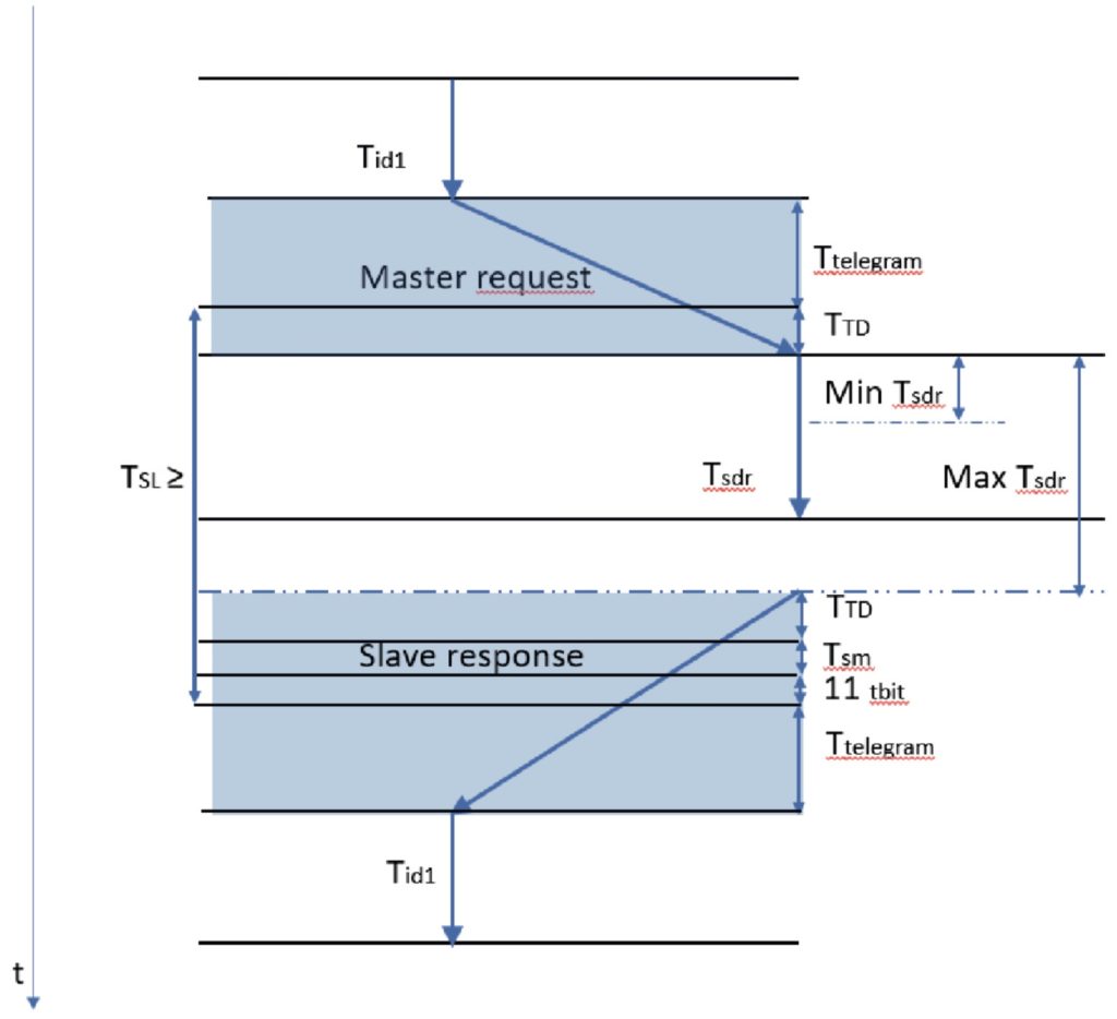
The process restarts after Tid1 has passed.
An example, please…
Typical values are:
Ttd1 = 0.557 ns/m for copper wire = 0.8355 tbit/km = 0.1671 tbit/200m
Ttd2 = 1.5 tbit per repeater or FOL = 1.5×nFOLs
Ttd3 = 7.5 tbit per km of FO
So for a 1.5 Mbps baudrate with 200 meters of cable (no FO nor FOLs), Tsl is equal to:
Tsl1 = 2×Ttd + Max Tsdr + 11 tbit + Tsm
Where:
Tsm = 2 + 2×Tset + Tqui = 2 + 2×6 + 3 = 17 tbit
Ttd1 = 0.1671 tbit
Max Tsdr = 150 tbit (@1.5 Mbps)
Therefore, Tsl1 = 2×0.1671 + 150 + 11 + 17 = 178.332 tbit
PI’s recommended value for Tsl @ 1.5 Mbps is 300 tbit.
But if we additionally had a 4 km FO ring with 4 FOLs:
Tsl1 = 2×(Ttd1 + Tsd2 + Tsd3) + maxTsdr + 11 tbit + Tsm
Therefore, Tsl1 = 2×(0.1671 + 1.5×4 + 7.5×4) + 150 + 11 + 17 = 227.8342 tbit
Following this calculations it seems that the standard bus parameters recommended by PI are adequate.
But there’s another catch.
There’s always a catch…
Each station has a Tsl margin to transmit the first byte in each message cycle. But in each message cycle, the FO and FOL’s delay the transmission a few tbits. The Slot timer checks this and adjusts the timings continuously, but since each FOL from each supplier has different electronics, the Ttd adjustments and therefore the corresponding Tsl value is calculated differently.
In fact, each station has its own Ttd, since each one is separated from the master via different copper cable lengths, FO lengths, repeaters, and FOLs.
Furthermore, each station has its own Tsdr value, meaning that the Tsl should be large enough to accommodate even the slowest device in the network, this being the one with the highest Tsdr value.
So it becomes impossible to calculate precisely the exact value of Ttd. You end up using an empiric value. As for Tsl, it is also an empiric value, since it is derived from Ttd.
An inadequate Tsl value, especially one that is too small, can create havoc in the data exchange process.
As an example, when using Phoenix Contact FOLs in a 4 km FO redundant ring configuration (let’s say 4 OLMs) at 1.5 Mbps, the manufacturer’s recommended Tsl value is 647. That’s more than twice the standard PI value.
And another…
Some software engineering tools used for hardware configuration feature the possibility of defining the presence of repeaters or even FOLs and FO and use that data to make the corresponding adjustments in the bus parameters, but most don’t. Even in the ones that have this feature, it’s usually meant to be used with the manufacturer’s own FOLs, so it’s better to use the settings recommended by the maker of the FOLs you are actually using.
If the configuration software you are using doesn’t offer this feature, you’ll have to make the adjustments by yourself.
Finally, always remember to RT#M…
In conclusion, if you are using PROFIBUS DP FOLs, and especially if they are being used in combination with FO ring topology, you’d better check your FOL’s manual and adjust your bus parameters. Otherwise, you may end up using the default values, which are too small to use with the Ttd values required by the use of FO and the FOL’s. If you don’t take this into account, devices will be dropping from data exchange mode randomly, leaving you scratching your head.
Written by Mirko Torrez Contreras, Autex SA with input from Peter Thomas, Control Specialists Ltd.