Communication issues are often encountered on PROFIBUS networks, due to various factors such as reflections or electromagnetic interference (EMI). Malfunctions caused by these problems can easily be avoided if the main causes can be identified.
What disturbances can occur on a PROFIBUS network?
Electrical disturbances on an industrial plant can occur as a result of voltage overloads, voltage spikes, sags or transients. Noise (unwanted electrical signals, which distort or interfere with an original or desired signal) can also be quite common as a consequence of wrong grounding, bad cable shielding or the proximity to power cables.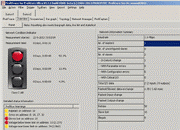
In a PROFIBUS network, these disturbances can affect the communication and generate malfunctions. Some of the many different kinds of issues that can occur include: losing communication to network devices, alarms, broken or damaged components, and power overload. Downtime is extremely detrimental as it can result in great losses and safety hazards at your facility. It is thus essential to take steps to avoid electromagnetic disturbances.
Questions to ask to prevent the most common failures on PROFIBUS
The most common malfunctions on PROFIBUS networks originate mainly from communication issues, signal reflections and electromagnetic interference. We can limit or altogether prevent these three events with a proper network design. In order to design a reliable and solid network we need to understand how these events can occur by asking ourselves some simple questions:
1. Can I avoid communication issues on PROFIBUS networks with a proper segment length?
Profibus International (PI) provides a range of guidelines and best practices regarding the design and installation of PROFIBUS networks, including how to reduce disturbances. Following these recommendations can significantly minimize the risk of interference.
On extended installations, PROFIBUS networks may have hundreds of nodes requiring a division in automated units and segmentation in different areas. Different processes require setting different transmission speeds (baud rate), which is possible with the PROFIBUS protocol.
As the baud rate changes, so does the maximum length of the cable. 1.5 Mbps is the most commonly used transmission speed (it is the case for 76% of our inspected applications), as this is the default speed when you create a new project in most PLC configuration tools. A network with 30 devices running at 1.5 Mbps has an average cycle time of less than 10 ms. If this cycle time is not necessary, it is recommended to reduce the transmission speed; when the transmission speed is lower, you can install longer trunk cables and longer spur lines, and the data is less vulnerable to electronic disturbances.
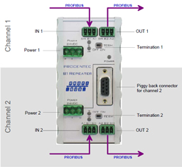
Increasing the baud rate also increases the possibility of communication errors. Unless it is necessary, we recommend using a lower speed to get the right balance between performance and reliability. However, when considerable lengths are required, a PROFIBUS repeater should be installed. Repeaters regenerate the electrical signal and are used to reach longer distances, both to the segment and the network.
2. What is the main problem to tackle on a PROFIBUS network?
The most common problem is the result of reflections of the signal, generated by missing active terminations or wear of the cables. A focus should be especially on cables: thanks to their internal structure, cables provide immunity against electromagnetic interference. If the cable is damaged or worn, it fails to offer protection.
On an existing network presenting reflections in the signal, we can try to figure out which cable segment is worn or broken using a protocol analyzer, such as PROCENTEC’s ProfiTrace. This allows you to determine the bus faults and make diagnostics of the PROFIBUS network on site (Read the Tutorial: What can I do with ProfiTrace?).
In the event that permanent monitoring of the network is needed, you can install a device that is connected 24/7. ComBricks is the ideal monitoring solution for this. It is a modular tool for permanent monitoring and diagnostics of PROFIBUS networks. With ComBricks you can both analyze failures from a safe area and intercept the signal reflections, in addition to preventing problems thanks to the straightforward alert system via email.
3. Why are electromagnetic interference detrimental for communication?
Electromagnetic Interference (EMI) is a permanent or transient alteration in an electrical signal, due to an electric or magnetic field detected on the transmission cable or in the device. The electric field is generated by a simple voltage difference, while the magnetic field is generated whenever there is a stream of current. Since devices process electrical signals, they may be sensitive to such interference.
RS-485, the physical layer used by the PROFIBUS protocol, is formed by a cable with two twisted wires and a shielding braid. The signal transmitted is the result of the difference between the voltages of the two wires.
Although a transmission of this type is very reliable, some signals could be altered in amplitude, generating an error in communication. EMI can cause retransmissions of information or even downtime, which can lead to financial losses. To avoid interference, you can take some precautions, such as:
- Use shielded power cables and make sure the installation was carried out properly (with enough air or metal separation between power and signal cables).
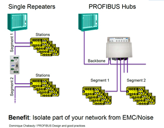
- Make sure that electromagnetic interference does not spread to other segments by installing a certified multichannel repeater. This can prevent interference propagation and isolate noises on a single bus segment.
 4. How do I know which device is right for my facility?
Certification of PROFIBUS devices is not mandatory. Nevertheless, it is smarter to choose devices designed and certified to operate in PROFIBUS while meeting certain reliability requirements. Certified devices behave as ‘Faraday cages’, i.e. they are not disturbed by external factors and usually do not influence each other. This means that with certified devices we can considerably reduce electromagnetic interference.
- Consider setting the cable redundancy, using devices that support this feature (such as ProfiHub B5+R by PROCENTEC). Cable redundancy is useful for increasing the reliability of your network. In fact, it increases plant availability, as the failure of one PROFIBUS cable has no effect on communication.
- In the design of an installation subject to big interference and placed on a large area, consider using fiber optic cables that can ensure transmission across several kilometers and high immunity against electromagnetic interference. With a ring topology it is also possible to ensure the continuity of communications, even in the case of issues on one of the network devices. When in doubt on the type of configuration, it is recommended to ask PROFIBUS-certified experts in your country.
If we are facing issues on an existing installation, we can try to identify reflections and electromagnetic interference. What is the best tool to use for this?
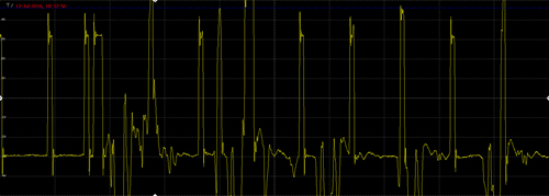
To pinpoint trouble segments, we must use a network analyzer with an oscilloscope in order to control the shape of the signal wave. The signal wave has a different size depending on the issue. In particular, the wave usually has an anomalous peak in the case of electromagnetic interference.
Above, we have already mentioned ProfiTrace: a powerful mobile analyzer for PROFIBUS networks. This tool enables the simple identification of electromagnetic disturbances.
In short, we can safely say that the initial design of a PROFIBUS network is essential for preventing issues such as reflections or electromagnetic interference, which are the cause of many malfunctions. Each malfunction, even if small or sporadic, results in high losses. It is therefore important to understand the origin of malfunctions and to grasp the basic principles to be followed in the choice of devices and cables.
A proper network design, in combination with the installation of appropriate equipment, form the basis in the creation of an upgraded reliable and long-lasting infrastructure or the expansion of an existing network. During the normal operation of the plant, the stability of the network can change with time due to environmental conditions, resulting in cable wear. In order to ensure the integrity of the PROFIBUS network, it is thus crucial to regularly perform diagnostic activities using the correct tools.
This article from PROCENTEC originally appeared on their website.